*UPDATE* October 18th: I have gotten the ESPixelStick v3.0rc2 firmware to compile and load, and am no longer using the original code below. I will leave it up as it may still be of use to others. Special thanks/shout-out to Bill Porter and Shelby Merrick for their assistance in getting it to compile.
In previous years, I’ve had to run a fairly long length CAT5 cable from my computer inside the house, out to my controllers. This was always a pain to setup each season because of the route I have to take; basically halfway around the house, through a crawlspace, then the basement and finally up through the floor to my show computer. I needed to come up with an easy, cheap solution to eliminate this cable entirely.
ESPixelStick by Shelby Merrick
After researching for a while I came upon a project called the ESPixelStick by Shelby Merrick. His design uses a basic ESP8266 wifi module to receive E1.31 DMX data, and then translates it into one of many other formats, mainly for RGB LED pixels/strips (WS2811 or similar). In later software, it appears that he added the ability to output raw DMX instead of translating into pixel protocols, as I planned on using this device with 2 Light-O-Rama controllers (CTB16PC). His design led me to look into the Espressif WiFi modules further.
Espressif has several WiFi modules on the market, with a builtin microcontroller which is able to run some code on board. There is also a library/toolset available to integrate these right into the Arduino IDE, which makes them extremely easy to program.
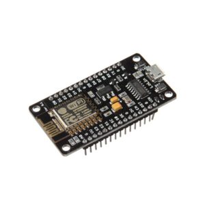
NodeMCU Development Board
After doing some more research I ultimately settled on using a NodeMCU development board, which utilizes an ESP-12 from Espressif, and has built-in power regulation (it can run from 5 to 14 volts DC). I have used these boards before for several IoT (Internet of Things) projects, and am comfortable/familiar with them. This board can be found on eBay from several foreign based vendors for under $5. I also found some RS-485 converter modules on eBay for around $3, these will be needed to convert the data from the NodeMCU board to standard DMX 512 data, which is a protocol that uses the RS-485 standard; as well as an RJ-45 jack module, since I planned on using this with my Light-O-Rama controllers.
Developing the code was fairly easy, thanks to the availability of arduino libraries from several sources. Without those libraries, this project would have taken a lot longer to put together. Ultimately, I came up with the following code, which works great, although I am still considering it a Beta version. If you end up using this code/project, and discover any problems, please shoot me a message.
#include
#include
#include

// User defined options
const char ssid[] = "WIFI_SSID";         /* Replace with your SSID */
const char passphrase[] = "WIFI_PASS";   /* Replace with your WPA2 passphrase */
const int dmxUniverse = 1; /* Replace with your DMX universe */

// Expert User options, DO NOT CHANGE unless you absolutely know what are doing ** POSSIBLE SEVERE DAMAGE TO HARDWARE **
const int redPin = #; // PWM Output pin for RED LED
const int greenPin = #; // PWM Output pin for GREEN LED
const int bluePin = #; // PWM Output pin for BLUE LED
int redLevel, greenLevel, blueLevel;
int redNow = 0;
int greenNow = 0;
int blueNow = 0;
int state = 0;

E131 e131;

void setup() {
    DMXSerial.init(DMXController);

    pinMode(redPin, OUTPUT);
    pinMode(greenPin, OUTPUT);
    pinMode(bluePin, OUTPUT);
    Serial.begin(115200);
    delay(10);

    /* Choose one to begin listening for E1.31 data */
    e131.begin(ssid, passphrase, dmxUniverse);               /* via Unicast for Universe 1 on the default port */
    //e131.beginMulticast(ssid, passphrase, 1); /* via Multicast for Universe 1 */
}

void loop() {
    /* Parse a packet */
    uint16_t num_channels = e131.parsePacket();

    /* Process channel data if we have it */
    if (num_channels) {
        Serial.print("Universe ");
        Serial.print(e131.universe);
        Serial.print(" / ");
        Serial.print(num_channels);
        Serial.print(" Channels | Packets: ");
        Serial.print(e131.stats.num_packets);
        Serial.print(" / Sequence Errors: ");
        Serial.print(e131.stats.sequence_errors);

        for (int i = 0; i < num_channels; i++) {
          int j = i * 3;
          DMXSerial.write();
        }
    }
}
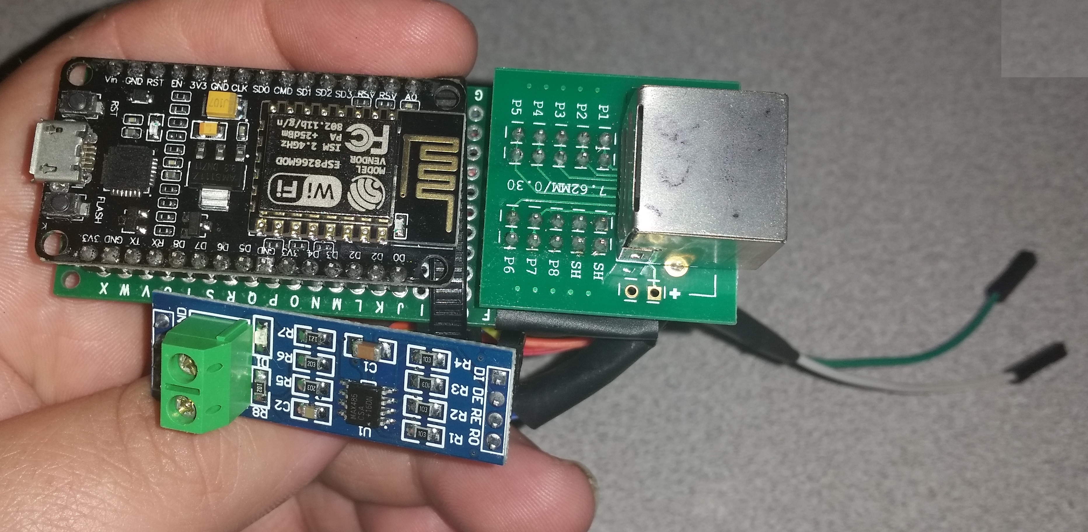
Prototype Hardware
The final prototype hardware was put together like this. I do have plans to re-design the hardware down to the board level, adding some voltage isolation, and eliminating all the loose wires. The final version will have both an RJ-45 as well as screw terminals for DMX out, and screw terminals for 5V DC power in. When completed, I will update this post to include links to OSHPark to order the boards, and either DigiKey or Mouser to order the component bill of materials.
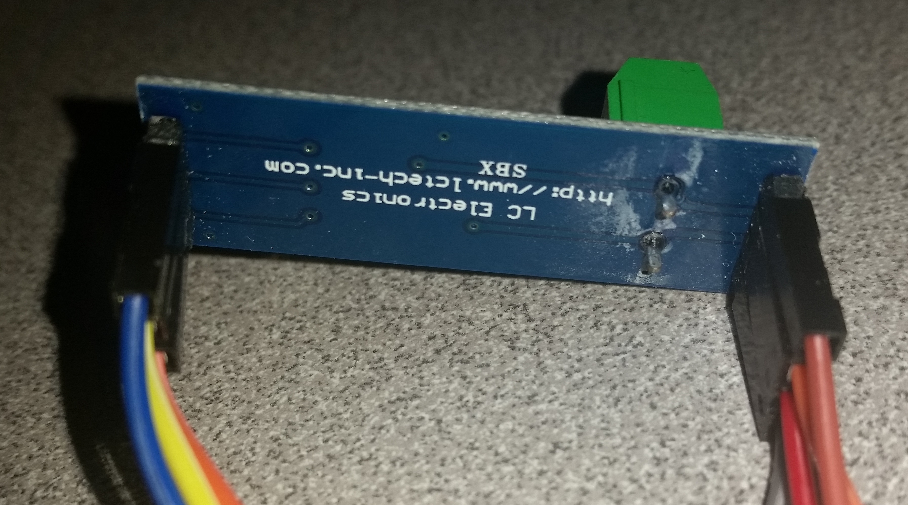
RS-485 Converter Module
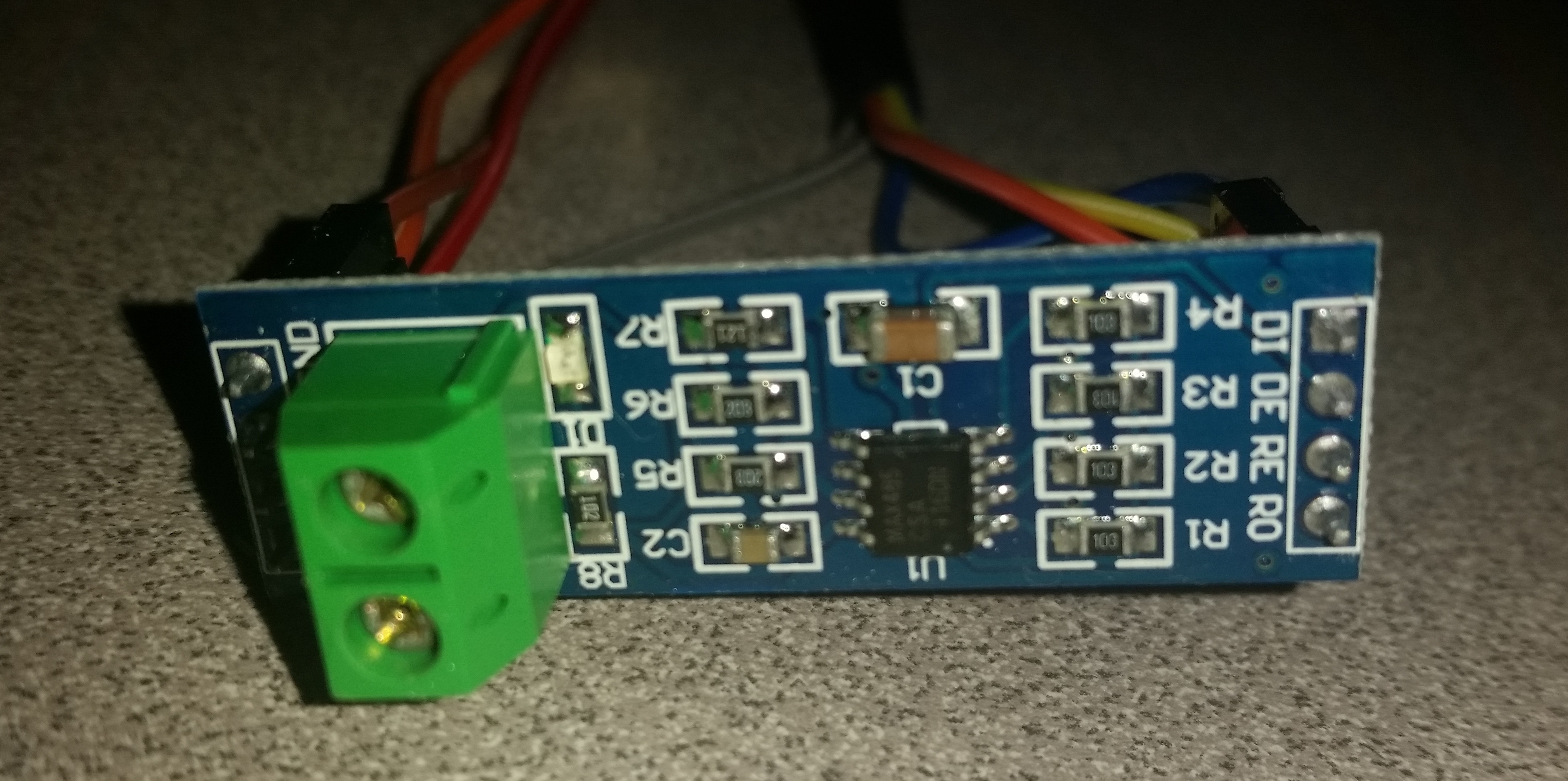
RS-485 Converter Module

Side/Wiring View

Prototype Hardware
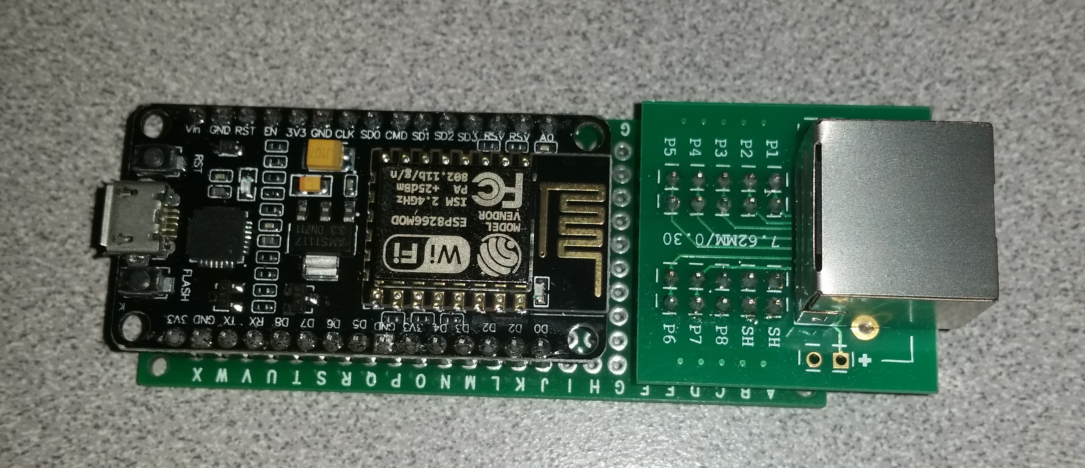
Prototype Hardware
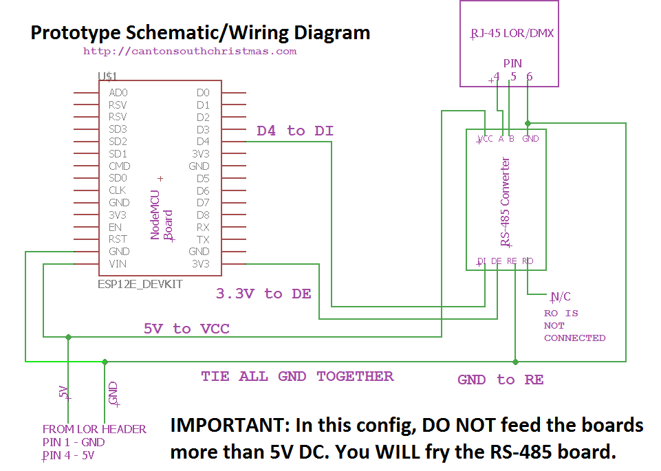
Prototype Schematic/Wiring
This hardware/code is theoretically able to handle up to 512 channels (1 full DMX universe). I have only tested it using 32 channels, 2x 16 channel LOR CTB16PC boards in daisy chain config. You may or may not require a resistor at the last board/device on a daisy chain to eliminate interference.
If you have any questions/comments, please enter them below or email me: [email protected]